In the field of industrial field control, PLC is the key equipment in the frequency conversion control cabinet. Beginning with the country’s continuous increase in investment in the water supply industry, the level of automation is also increasing, and the application of PLC in the water supply industry is also gradually increasing. The touch screen matches with the PLC, which makes the application of PLC more flexible. At the same time, parameters can be set, data can be displayed, and animation can be used to describe the automation process, so as to visualize the application of PLC.
Frequency conversion water supply has become the mainstream of the water supply industry, and it is an important means to ensure constant pressure in the water supply network. The perfect network communication engineering of modern frequency converter (VFD), synchronous operation of motors, remote centralized control and online monitoring provide necessary support. Through the touch screen connected with PLC, the control can be more intuitive, and the operation is more simple and convenient. Combining PLC, touch screen and VFD, VFD is controlled by communication to realize frequency conversion and constant pressure water supply.
System Structure
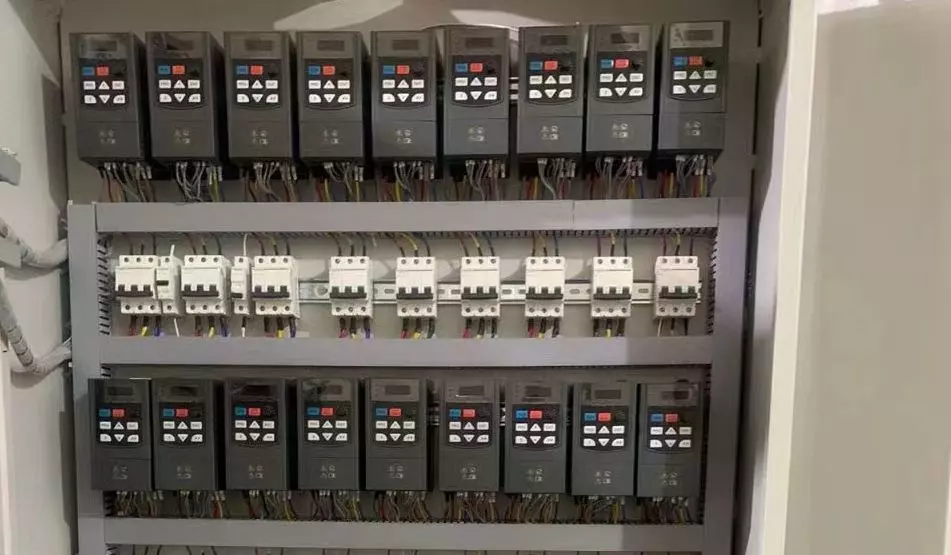
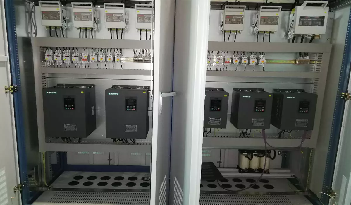
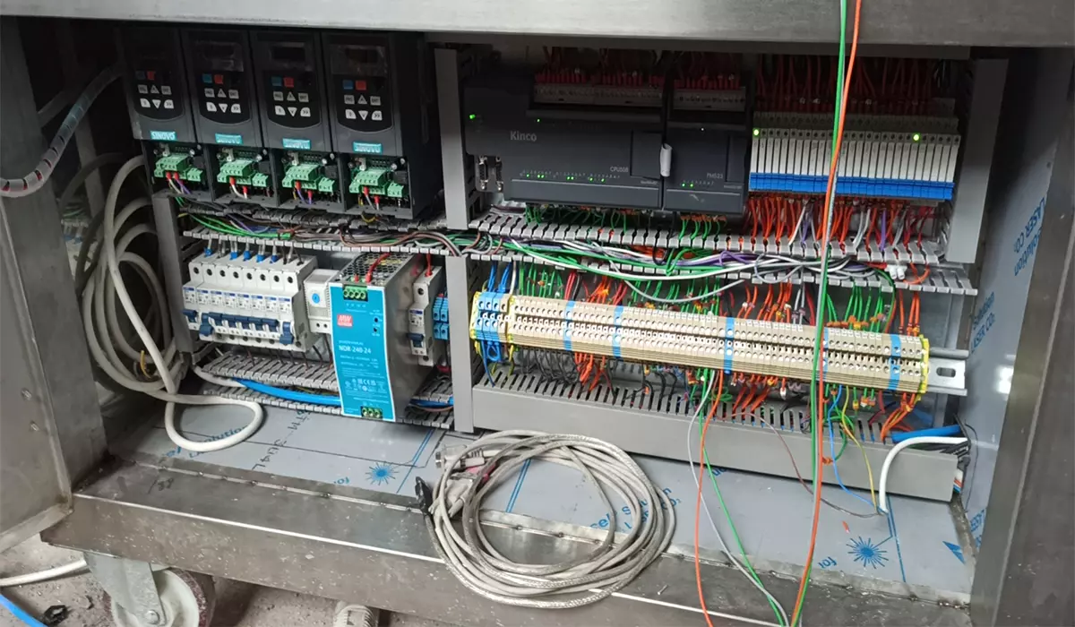
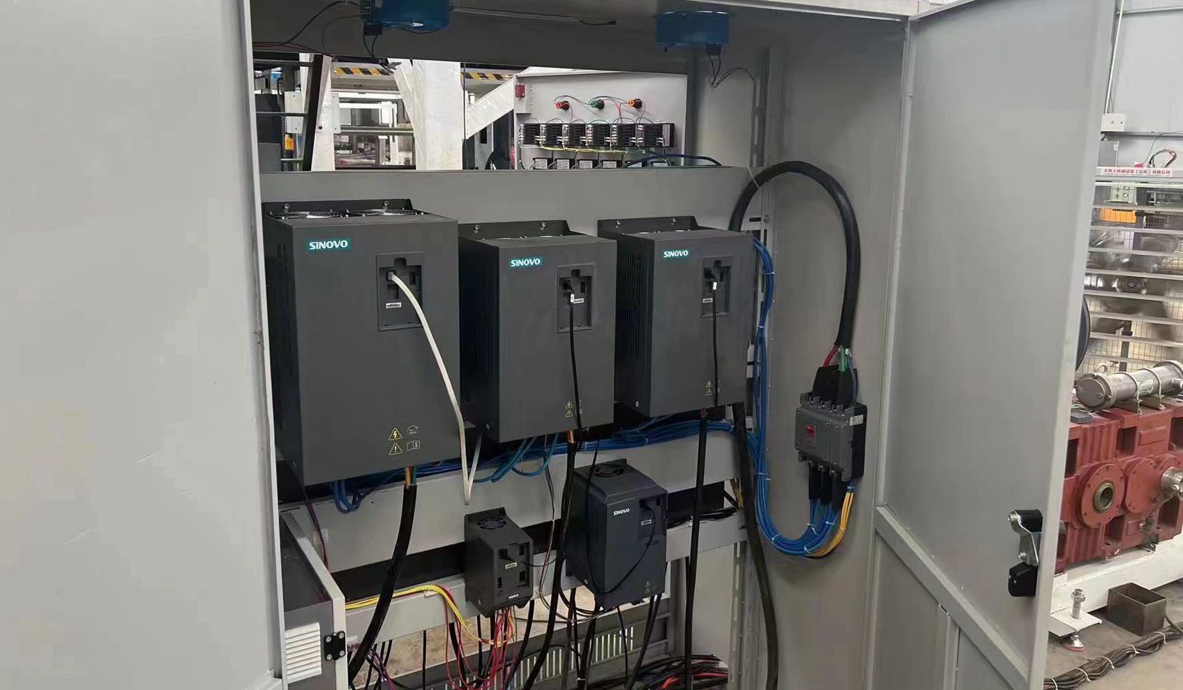
The frequency conversion water supply system is mainly composed of PLC, VFD, touch screen, pressure transmitter, power supply and control circuit and water pump unit. Users can control the operation of the system through the touch screen, and can also understand and control the operation of the system through the indicator lights, buttons and switches on the control cabinet panel. Through the pressure transmitter installed on the outlet pipe network, the outlet pressure signal is converted into a standard signal of 4 ~ 20mA or 0 ~ 10V, and sent to the built-in PID regulator of PLC. After the PID calculation, it is compared with the given pressure parameter, and the calculation frequency is output to the VFD. The system adjusts the water supply by controlling the speed of the water pump through the VFD. According to the different water consumption, the PLC frequency outputs a given operating frequency VFD, thereby adjusting the speed of the water pump to achieve constant pressure water supply. The internal program set by the PLC drives the output of the I/O port switch to switch the AC contactor group, thereby coordinating the number of pump motors in operation, and completing the start and stop of the motor, frequency conversion and power frequency switching. By adjusting the number of motors in operation and controlling the frequency conversion speed of one motor in the motor unit, the working pressure of the system pipe network is always stable, so as to achieve the purpose of constant pressure water supply.
Working Principle
The system has two modes of operation: manual and automatic. In manual mode, the operation of the pump is controlled by the start and stop button on the control cabinet, which can control the start and stop of 1 # – 3 # pumps according to the needs. This mode is mainly used for equipment debugging, automatic fault and maintenance. During automatic operation, firstly, the 1# water pump operates with variable frequency, and the VFD output frequency rises from 0HZ. At the same time, the PID regulator compares the received signal with the given pressure and sends it to the VFD for control. If the pressure is not enough, the frequency rises to 50HZ, the program set by the PLC drives the I/O port switch output, and switches the AC contactor group, so that the frequency conversion of the 1 # pump is quickly switched to the industrial frequency, and the frequency conversion of the 2 # pump is started. If the pressure still does not reach the set pressure, the frequency conversion of the 2 # pump will switch to the working frequency, and the frequency conversion of the 3 # pump will start. If the water consumption decreases, the PLC control starts to stop the pump from the first pump, and at the same time, the system runs smoothly according to the PID adjustment parameters, and always maintains the pipe network pressure.
In the event of a momentary power failure, the system will stop operating. After the power supply returns to normal, start it manually, and the system will automatically return to the initial state and start running. The automatic frequency conversion function is the most basic function of the system. The system automatically completes the entire operation process of starting, stopping, and cycle frequency conversion of multiple pumps.
Setting of device parameters
Before communication, the communication parameters of PLC, touch screen and VFD must be set correctly. The system is defined as Modbus protocol, the baud rate is 9600, the data bit is 8, no parity, and the stop bit is 1. In addition to setting communication parameters, VFD also needs to enable “free stop” to protect the motor.
PLC communication parameter setting: twdlcaa 24 drf-hardware-port-port setting, port parameter setting in port setting; touch screen communication parameter setting: IO manager-Modbus RTU01 [COM1]-Modbus device, double-click “Modbus device” to set communication parameters .
PLC control system
The system adopts frequency conversion lifting device, I/O points are 24 points, relay output, PLC programming adopts PLC special programming software Twidosoft. The software provides a complete programming environment for offline programming, online connection and debugging. In order to improve the cost performance of the whole system, the system uses the digital input and output of the programmable controller to control the start and stop of the motor, automatic input, timing switching, frequency conversion and fault alarm of the water supply pump, etc. In addition, the built-in PID of PLC gives analog signals such as motor speed, set pressure, frequency, current, voltage, etc.
In the field of industrial field control, PLC is the key equipment in the frequency conversion control cabinet. Beginning with the country’s continuous increase in investment in the water supply industry, the level of automation is also increasing, and the application of PLC in the water supply industry is also gradually increasing. The touch screen matches with the PLC, which makes the application of PLC more flexible. At the same time, parameters can be set, data can be displayed, and animation can be used to describe the automation process, so as to visualize the application of PLC.
Frequency conversion water supply has become the mainstream of the water supply industry, and it is an important means to ensure constant pressure in the water supply network. The perfect network communication engineering of modern frequency converter (VFD), synchronous operation of motors, remote centralized control and online monitoring provide necessary support. Through the touch screen connected with PLC, the control can be more intuitive, and the operation is more simple and convenient. Combining PLC, touch screen and VFD, VFD is controlled by communication to realize frequency conversion and constant pressure water supply.
System Structure
The frequency conversion water supply system is mainly composed of PLC, VFD, touch screen, pressure transmitter, power supply and control circuit and water pump unit. Users can control the operation of the system through the touch screen, and can also understand and control the operation of the system through the indicator lights, buttons and switches on the control cabinet panel. Through the pressure transmitter installed on the outlet pipe network, the outlet pressure signal is converted into a standard signal of 4 ~ 20mA or 0 ~ 10V, and sent to the built-in PID regulator of PLC. After the PID calculation, it is compared with the given pressure parameter, and the calculation frequency is output to the VFD. The system adjusts the water supply by controlling the speed of the water pump through the VFD. According to the different water consumption, the PLC frequency outputs a given operating frequency VFD, thereby adjusting the speed of the water pump to achieve constant pressure water supply. The internal program set by the PLC drives the output of the I/O port switch to switch the AC contactor group, thereby coordinating the number of pump motors in operation, and completing the start and stop of the motor, frequency conversion and power frequency switching. By adjusting the number of motors in operation and controlling the frequency conversion speed of one motor in the motor unit, the working pressure of the system pipe network is always stable, so as to achieve the purpose of constant pressure water supply.
Working Principle
The system has two modes of operation: manual and automatic. In manual mode, the operation of the pump is controlled by the start and stop button on the control cabinet, which can control the start and stop of 1 # – 3 # pumps according to the needs. This mode is mainly used for equipment debugging, automatic fault and maintenance. During automatic operation, firstly, the 1# water pump operates with variable frequency, and the VFD output frequency rises from 0HZ. At the same time, the PID regulator compares the received signal with the given pressure and sends it to the VFD for control. If the pressure is not enough, the frequency rises to 50HZ, the program set by the PLC drives the I/O port switch output, and switches the AC contactor group, so that the frequency conversion of the 1 # pump is quickly switched to the industrial frequency, and the frequency conversion of the 2 # pump is started. If the pressure still does not reach the set pressure, the frequency conversion of the 2 # pump will switch to the working frequency, and the frequency conversion of the 3 # pump will start. If the water consumption decreases, the PLC control starts to stop the pump from the first pump, and at the same time, the system runs smoothly according to the PID adjustment parameters, and always maintains the pipe network pressure.
In the event of a momentary power failure, the system will stop operating. After the power supply returns to normal, start it manually, and the system will automatically return to the initial state and start running. The automatic frequency conversion function is the most basic function of the system. The system automatically completes the entire operation process of starting, stopping, and cycle frequency conversion of multiple pumps.
Setting of device parameters
Before communication, the communication parameters of PLC, touch screen and VFD must be set correctly. The system is defined as Modbus protocol, the baud rate is 9600, the data bit is 8, no parity, and the stop bit is 1. In addition to setting communication parameters, VFD also needs to enable “free stop” to protect the motor.
PLC communication parameter setting: twdlcaa 24 drf-hardware-port-port setting, port parameter setting in port setting; touch screen communication parameter setting: IO manager-Modbus RTU01 [COM1]-Modbus device, double-click “Modbus device” to set communication parameters .
PLC control system
The system adopts frequency conversion lifting device, I/O points are 24 points, relay output, PLC programming adopts PLC special programming software Twidosoft. The software provides a complete programming environment for offline programming, online connection and debugging. In order to improve the cost performance of the whole system, the system uses the digital input and output of the programmable controller to control the start and stop of the motor, automatic input, timing switching, frequency conversion and fault alarm of the water supply pump, etc. In addition, the built-in PID of PLC gives analog signals such as motor speed, set pressure, frequency, current, voltage, etc.
continue reading
Related Posts
Variable Frequency Drives (VFDs) and motors are integral components in industrial automation, each serving distinct yet interconnected roles in controlling […]
Variable frequency motors (VFMs) are crucial in modern industrial applications due to their efficiency and precise control over motor speed […]
Variable Frequency Technology (VFT) is increasingly being recognized as a game-changer in the industrial automation sector, particularly in applications involving […]